THE MOBILE STACKING CONVEYOR
P STAPLES Pr Eng Bsc Mech Eng
OVERVIEW
There is no better example today of the mining industry moving into the 21st century than the
development of the Mobile Stacking Conveyor to form waste dumps in an ecologically sensitive
country.
The use of the MSC has allowed the construction of larger volume waste dumps with high moisture
content tailing aimed at eventually eliminating slime dames and thus high water usage.
Systems such as these are difficult to justify when one looks at the initial capital costs only.
Luckily, however, some progressive organisations are prepared to use management tools such as simulation,
financial modelling and life cycle costing to allow them to justify initial high capital costs
knowing that during the life of the mine, the rewards will be extensive.
This dissertation shows a typical system where considerable savings will be realised in the development
of such an installation.
INTRODUCTION
South Africa and South America has become the largest users of dumps for stockpiling mine waste,
tailings, overburden and the development of heap leach systems.
Areas such as ash dumps, tailings disposal, rehabilitation sites and minerals extraction have all
lent themselves to the formation of extensive dumping sites, usually being formed with the use of one
of the following systems:
- trucks and dozers
- grasshopper conveyors and spreaders
- shiftable conveyors and spreaders.
With the differentiation between the grasshopper and shiftable system usually being a function of
capacity and capital outlay.
With the development of high capacity heap leach pads for the extraction of minerals such as gold and
copper an alternative dumping procedure had to be found which allowed for improved control of the dump
site allowing for high speed operations on rapidly developed pads resulting in low ground bearing
pressures, which can be negotiated by the crawler system capable of travelling over such terrain, with
the ability to quickly develop the dump/pad.
To meet these requirements, the Mobile Stacking Conveyor (MSC) was developed and has proven itself very
cost effective in this field. Since its inception in the early 1980's the MSC has had outstanding
success in heap leach pad development, resulting in new opportunities for utilisation on similar
stockpiling systems.
To this end the waste dump formation and dump rehabilitation have been investigated as areas of
interest for the MSC.
Prior to delving into the application of the MSC, we would like to highlight the components that make
up the unit.
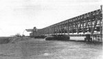
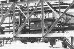
Figure 1
This picture shows a typical installation 200m long with crawlers mounted every 50m.
Note the closeness of the crawlers to the dump edge, allowing accurate placement of tailings
resulting in a very smooth dump surface suitable to allow the crawlers to negotiate the pad
without extensive dump surface preparation.
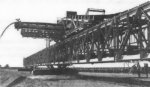
Figure 2
Here we see the tripper with its translating boom. The tripper itself can traverse the full length
of the MSC, being driven through an onboard drive, sheeve and rope configuration. The travel drive
is variable speed allowing controlled placement of tailings even with variable feed rates.
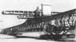
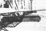
Figure 3
Another feature of the tripper translating boom is its ability to back stack and possibly top soil
as it advances. The translating boom propels itself forward, being able to reach 12m from the MSC
centre-line, thus improving ground drying time prior to travelling.
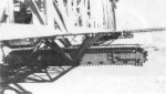
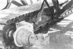
Figure 4
The heart of any machine of this type is the crawler. Here we have to cater for low ground bearing
pressures by designing a special crawler.
Commercially available crawlers are not practical nor economical for such a machine, therefore we must
custom design the unit to meet the specifications.
The actual design incorporates the principles of scraper chain design in the link construction,
making the unit economically viable, yet well proven in the mining environment.
Figure 5
Figure 5 above and Figure 6 below give a closer view of the crawler levelling and driving mechanism.
The drive is a conventional hydraulic unit, giving proportional speed and thus accurate alignment
control of the total system.
Figure 6
Figure 7
Another unique feature of the MSC is the return belt, which has been formed into a pipe.
The main reason for this is to eliminate spillage on the return belt strand allowing protection of
the crawlers and power packs.
MODE OF OPERATION
The MSC is flexible in that it can move linearly, radially, up or down a slope without having to follow
a horizontal line.
For horizontal movement, each MSC bridge is equipped with crawlers to maintain alignment, hydraulic
cylinders to maintain level, (thus assisting the passage of the travelling tripper over the bridge
connections). These alignment functions are controlled via a set of sophisticated field instruments
coupled to a computerised control system.
To further assist the stacking of material, the tripper itself is equipped with a translating boom
which allows for accurate placement of the ground in front or behind the MSC. The translating boom is
programmed to detect the face of the dump via a laser probe and is able to layer the material accurately
along this face. On completion of a stacked layer, the boom extends and the process is repeated until
the translating boom extends the full length.
At this point, the total system is advanced forward on the previously laid ground, it is able to
negotiate the small ridges in the dump surface. Therefore, it is not normally necessary to level the
ground prior to movement, however, good practise is to ensure no excessive piles lie in front of the
tracks and improved operation will be obtained by running a grader in front of the MSC prior to
movement.
Control of movement, as stated previously is achieved via instrumentation and PLC control. The crawlers
are advanced together using limits to ensure alignment between bridges. After relocation the total
bridge is accurately aligned and levelled again automatically to an accuracy of ±5mm in both
planes.
The moving mode is achieved by the use of what could be called a controlled shuffling action of the
crawlers. Advancing one of the terminal point crawlers is immediately detected as an out of alignment
between the bridge sections which is identified by the linear transducer at that junction. (Refer to
Figure 8.) When this alignment exceeds a pre-defined value (miliamp signal) the next crawler in line
sets off to catch the first unit. Through the use of proportional control, the drive detects a worsening
or improvement of the aligmnent conditions and reacts by slowing or accelerating the crawler drive
accordingly.
Should the condition of misalignment worsen to a further pre-defined limit, the system is shut down
to prevent damage to the structure and connections.
Assuming correct operation, the first terminal crawler is advanced in this manner until it reaches its
required position with all remaining crawlers following suit.
Each crawler is then shut down in the correct position and finally the total bridge is hydraulically
levelled again from a pre-defined base level using two hydraulic cylinders. (Refer Figure 9.)
Figure 8
Figure 9
APPLICATIONS FOR THE MSC
The MSC is used primarily for stacking large volumes of material automatically in a pre-defined pattern.
It requires little operational control and relocation time. It is ideal for materials with large
moisture contents which cause problems with conventional dump stacking. Sites such as tailings dumps
are ideal for the MSC in that they require long drying times to stabilise the dump prior to further
stacking of materials. Therefore, because the material is laid in thin layers over large areas it is
possible to travel on it sooner than with a conventional stacking system.
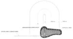
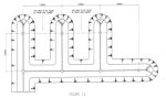
To highlight the layout advantages, we have included a conventional stacking system as indicated in
Figure 10. To achieve the necessary filling of a dump of this type requires extensive transfers,
multiple machines and highly intensive labour force. Compare this to a typical MSC layout (Figure 11)
which eliminates most of the transfers, reduces the number of machines and generally streamlines the
operation.
Correctly setting up a MSC dump configuration requires an initial berm to install an advancing spreader,
the MSC then follows the spreader profile, being able to climb 20% slopes to the required dump height,
thus the dump formation is simple to automate and control allowing extensive savings in downtime for
MSC movements and therefore dramatic improvements in availability and eventually costs.
To highlight the overall savings in the use of this type of system a comparison was drawn between four
systems commonly used in dump formation:-
- pumping,
- trucking & dozing,
- Mobile Stacking Conveyor,
- shiftable conveyors & spreaders.
This comparison was undertaken along the lines of a capital and O&M costing.
It can be seen that the initial capital cost of the stacker and MSC system were very similar, however,
after only five years the MSC is showing extensive savings.
Trucking, which shows low initial capital costs, quickly catches up on the other systems, even at a
fixed cost per ton.
Therefore, applying the philosophy of flexibility to the trucking scenario is the only way it can
compete in this type of application.
CONCLUSION
In conclusion, it can be appreciated that in the mining and beneficiation processes of today to
compete in the world market extensive efforts must be made to optimise operations by improving
efficiencies.
The MSC system was originally developed to offer the formation of cost effective heap leaching pads
which allowed a mine to be profitable even with grades of ore of less than 2gm/ton.
Figure 10
| |
|
CAPITAL |
OPERATING & MAINTENANCE
REQUIREMENTS
|
O&M
COSTS |
Scheme
|
Descrip-
tion
|
Capital used/year
R'000
|
Absorb.
Power
kW |
Fuel
Used |
Water
Used
kLi |
Labour
Require.
Type |
Trans-
port
used |
Dump
Equip-
ment |
Main-
ten-
ance |
Oper-
ating |
| |
|
0 |
1 |
2 |
3 |
4 |
|
|
|
1 |
2 |
3 |
4 |
|
|
|
|
1
|
Pumping
Housing
Allowance |
8976
1237 |
250
|
1275
|
0
|
1353
|
115
|
0
|
167
|
1
|
3
|
16
|
6
|
1
|
2455425
|
656214
|
4664275
|
2
|
Trucking
Housing
Allowance |
6570
1624 |
0
|
1855
|
0
|
2449
|
120
|
0
|
5
|
1
|
2
|
8
|
24
|
1
|
2866500
|
270758
|
3999747
|
3
|
Mobile
Bridge
Spreader
Housing
Allowance
Royalty
Allowance
4% |
9650
1096
386 |
2000
|
0
|
0
|
0
|
638
|
0
|
10
|
1
|
2
|
16
|
4
|
1
|
0
|
563000
|
1276240
|
4
|
Crawler
Mounted
Stacker
Housing
Allowance |
12120
1219 |
2000
|
750
|
0
|
990
|
828
|
0
|
10
|
1
|
1
|
20
|
4
|
1
|
837675
|
647000
|
2330365
|
Annual
Capacity: |
3518250 ton/year |
Inflation
Factor: |
0 |
OPERATING YEARS |
Sch-
eme |
Descrip-
tion |
0
|
1
|
2
|
3
|
4
|
5
|
|
| |
|
Cap-
ital |
Oper-
ating |
Cap-
ital |
Oper-
ating |
Cap-
ital |
Oper-
ating |
Cap-
ital |
Oper-
ating |
Cap-
ital |
Oper-
ating |
Cap-
ital |
Oper-
ating |
Totals
R'000 |
1
|
Pumping
Per ton |
10213.00
|
5320.49
1.51 |
250.00
|
5320.49
1.51 |
1275.00
|
5320.49
1.51 |
0.00
|
5320.49
1.51 |
1353.00
|
5320.49
1.51 |
0.00
|
5320.49
1.51 |
45014
|
| |
|
|
|
|
|
|
|
|
|
|
|
|
|
|
2
|
Trucking
Per ton |
8194.00
|
4270.51
1.21 |
0.00
|
4270.51
1.21 |
1855.00
|
4270.51
1.21 |
0.00
|
4270.51
1.21 |
2449.00
|
4270.51
1.21 |
0.00
|
4270.51
1.21 |
38121
|
| |
|
|
|
|
|
|
|
|
|
|
|
|
|
|
3
|
Mobile
Bridge
Spreader
Per ton |
11132.00
|
1839.24
0.52 |
2000.00
|
1839.24
0.52 |
0.00
|
1839.24
0.52 |
0.00
|
1839.24
0.52 |
0.00
|
1839.24
0.52 |
0.00
|
1839.24
0.52 |
24167
|
| |
|
|
|
|
|
|
|
|
|
|
|
|
|
|
4
|
Crawler
Mounted
Stacker
Per ton |
13339.00
|
2977.37
0.85 |
2000.00
|
2977.37
0.85 |
750.00
|
2977.37
0.85 |
0.00
|
2977.37
0.85 |
990.00
|
2977.37
0.85 |
0.00
|
2977.37
0.85 |
34943
|
| Power Costs |
R |
0.114 Per kW hr |
| Fuel Costs |
R |
1500 Per kLi |
| Water Costs |
R |
0.33 Per kLi |
| Transport |
R |
36000 Per Bakkie/Year |
| |
|
|
| Labour |
|
|
| 1 Supervisor |
R |
50000 Per Year |
| 2 Artisan |
R |
50000 Per Year |
| 3 Labourer |
R |
26000 Per Year |
| 4 Drive |
R |
26000 Per Year |
| |
|
|
| Housing |
|
|
| 1 Supervisor |
R |
110000 Per House |
| 2 Artisan |
R |
53000 Per House |
| 3 Labourer/Driver |
R |
44000 Per House |
NPV ANALYSIS |
Year |
Scheme 1 |
Scheme 2 |
Scheme 3 |
Scheme 4 |
|
0 |
15533 |
12465 |
12971 |
16316 |
|
1 |
5570 |
4271 |
3839 |
4977 |
|
2 |
6595 |
6126 |
1839 |
3727 |
|
3 |
5320 |
4271 |
1839 |
2977 |
|
4 |
6673 |
6720 |
1839 |
3967 |
|
5 |
5320 |
4271 |
1839 |
2977 |
|
| |
|
|
|
|
|
| |
8.0% |
8.0% |
8.0% |
8.0% |
|
| |
|
|
|
|
|
| |
39096 |
32906 |
22167 |
31427 |
NPV |
| |
45014 |
38121 |
24167 |
34943 |
PREVIOUS |
Analysis, such as that carded out in Figure 12, highlights the cost inaccuracies associated with using
capital cost approach to "KIT" selection. The South Africa mining industry is benefiting from its
minerals wealth by adopting extensive modelling procedures aimed at maximising efficiency to guarantee
high pay-backs for capital employed.
The initial capital cost approach to process layout and KIT selection has finally been exposed
as a formula for destruction with companies selecting on bottom dollar rapidly failing by the
wayside when international competition moves onto the scene.
The MSC is conclusively shown as a system selection adopted with the use of proven financial
and simulation modelling techniques guaranteeing high productivity and low operating and
maintenance costs. Therefore, the days of justifying a truck or train operation on the basis
of flexibility is an excuse to justify a company's inability to forward plan.
Figure 11
Figure 12