Simulation Benefits Underground
Mine infrastructure Design
A. Lebedev and P. Staples, Republic of South Africa
Summary
The application of simulation modelling to the design of the entire materials handling system in a new
underground mine is discussed. Two tasks were solved with the model: sizing capacities of capital
equipment items to meet the future performance target; and phased selection of the incline conveyor
belt depending on the mine output, The effect of the equipment availability was also analysed. Battery
limits of the model were underground ROM bunkers receiving ore and waste delivered by the
dump trucks in
the front; and ore and waste surface reclaim conveyors in the back. Witness
simulation software was used to conduct the study, which allowed the sizes of key equipment to be
adjusted, and an incline belt replacement schedule to be recommended.
1. Introduction
Simulation modeling has been applied for the design of materials handling systems since the early
1960s. Abundant literature has been published since then describing numerous applications and
achievements of simulation for the industry. Good reference sources featuring reviews of published
papers as well as examples of mine simulations in particular, are given in the References [1-4]. The
applicability of discrete and continuous simulation modeling techniques for bulk conveying systems
is discussed in [5], where the quality of approximation of a theoretical conveyor was analysed for
feed functions of different types. Some of the case studies of simulating materials handling systems
in the mines appear, for example, in [6-8].
Typically, simulation modeling of materials handling systems is primarily used to achieve the
following objectives:
- To quantify the required capacity of a materials handling system to achieve a given production
target (normally at the design stage of a new operation or at an upgrade stage of an existing one).
- To quantify the maximum possible production throughput at a given capacity of a materials
handling system (normally involves a review of management policies in an existing operation, provided
that the hardware is fixed but needs to be improved in terms of utilisation or other operational
criterion).
- To identify bottlenecks in the materials handling system and to improve throughput (in case of an
existing operation, this task may be associated with some changes external to the materials handling
system, for example with a deviation in the material quality resulting in a larger fraction of waste,
or with a different arrival pattern and size of trucks).
The list can be extended further, however, it essentially comes down to saving Capex (Capital
Expense) as in the first item above, or operating cost in item two, or keeping up production and sales
as in item three, and in general, to improving profitability of either a new or an existing operation.
Other methods like linear programming can also be applied to achieve the same objective but
simulation is known for its advantage of more accurate accounting for the real world uncertainty and
diversity. The very fact that simulation enjoyed an almost 40-year application history and
continues to grow, proves its own success.
This simulation study had an objective as in item one above for one of the existing
South African mines which is busy sinking a new shaft and which will have to establish an entire
underground and surface infrastructure.
To accomplish the task, Witness simulation software, available from the Lanner
Group, was selected because of the following reasons:
- Mining several grades of ore which may not be contaminated and sharing some of the materials
handling resources, caused the need to implement complex operating procedures which cannot be
directly modelled using the standard logical elements available in most of the simulation software.
Witness has a built-in programming language which allows the creation of most
tricky logical rules like "if.... Else If .., Then" and customized functions.
- The need to interface discrete and continuous modelling constructs (e.g. dumptrucks and
continuously operated conveyors), and Witness can handle it using "Fill" and "Empty"
rules, which are usually unavailable in other simulation languages.
A preliminary design of the entire materials handling system was supplied for the simulation
exercise, with all capital items sized, and the task was to verify capacities for the start-up and
projected production target. The system concerned includes "fixed" installations like underground
crusher and bunkers whose capacity cannot be changed and which had to be sized for the future mine
production from the start.
An incline conveyor, one of the capital-intensive items in the system whose structure also needs to be
sized adequately for the future output, could, however, be operated at a lower speed in the beginning.
The belt can be replaced later to meet escalating production.
The simulation study had two approaches:
- Size all "fixed" capital equipment items for the future production target.
- Size the incline belt for various mine outputs and recommend replacement timescales.
2. Mine Development Procedure
In order to reduce the cost of sinking the shaft, a suitable method of using the incline conveyor had
to be prepared to allow the belt to advance down the shaft following the mining process and convey
waste to the surface. This procedure required the provision of a temporary conveyor take up at the
surface, which will eventually be moved to the tail, and a temporary truck loading facility at the
final head position.
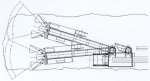
To assist with the shaft development, a temporary (sacrificial) belt will be used during the sinking
process, which needs to be replaced when the conveyor reaches its final position. It will be fed by a
"piggyback" conveyor following the advancement of a tunnel-heading machine as shown in Figs. 1,2.
Fig 1: Top view of the tunnel-heading machine and a "piggyback"
conveyor feed
hopper
Fig 2: Side view of the tunnel-heading machine and a "piggyback"
conveyor feed
hopper
Once the incline shaft is fully established, the initial phase of mine development will generate
primarily waste, and ore mining will gradually grow starting with low tonnage. The long term mining
plan projects a 100% growth over the years until the mining operation reaches a steady state. In order
to avoid excessive Capex associated with the replacement of a temporary incline belt with a new one
from the start, it was necessary to verify how long the temporary belt can deliver the mine production.
It was also required to cheek whether a phased approach could be used in introducing a new incline
belt, i.e. use a lower rated new belt in the beginning and a bigger one at a later stage, as per the
second objective of the simulation study.
3. Overview of the Simulation Model
Mining will take place in a stope with three development faces, and in the beginning of every shift
ore from all of them will be sampled and graded. Up to three different grades of ore can be mined
within a shift, and quantity of generated waste can reach 10% of the total production. Ore and waste
will be removed from the stope by dump trucks to the tipping point with four ROM bunkers, three of which
are dedicated to ore and the fourth one to waste, Every shift allocation of ore bunkers to various
grades of ore may change depending on the results of sampling, which was simulated as a customised
discrete distribution reflecting real fractions of the mined ore grades. ROM bunkers were the front
battery limit of the simulation model.
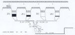
From the ROM bunkers ore and waste will be discharged by means of vibrating feeders to a screen, and
the coarse fraction will be crushed and then conveyed further to the crushed ore bunkers along with
the fines. The underground crushing and screening section is shown in Fig. 3.
Fig 3: Underground crushing and screening section
To simulate the worst case operating scenario, dump trucks arrived randomly to the tipping point and
delivered ore or waste throughout the whole shift, depending on the random sampling outcome. This
excluded a controlled delivery sequence, namely ore first and then waste or other way around.
Withdrawal of ore from the ROM bunkers is priority number one, and is controlled in a way to minimise
the number of movements of a tripper depositing crushed ore and waste into crushed ore bunkers. ROM
ore bunkers should be clear by the end of the shift, cleaning of the waste ROM bunker may be done in
the beginning of the following shift while ore bunkers are busy accumulating material before
discharge.
To avoid contamination, a clearing time was allowed for in this part of the model which was equal to
the transport delay time plus the time to relocate an automatic tripper, i.e. once a specific ROM
bunker finished discharging, the next bunker was not allowed to start discharging before the entire
chain from the ROM bunkers to the crushed ore ones was cleared.
The following operating procedure was simulated in this part of the model:
- Trucks start arriving and dumping materials in the ROM bunkers temporarily dedicated to those
materials during the current shift (bunker A5-4 is always dedicated to waste).
- Once the level in a bunker exceeds a preset value, discharging of a specific material starts and
lasts until the bunker is emptied, and that moment in time is captured. Other bunkers "wait" for the
system to become available.
- Once the clearing time for this section expires, and if the level in any other bunker has reached
the preset value, discharge from that bunker can commence.
- By the end of the shift, ore ROM bunkers will be emptied regardless of their content.
- Only when all the ore bunkers are cleared, can the waste one be emptied.
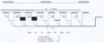
The underground crushed ore bunkers section comprises seven bunkers, each dedicated to
a specific material, namely the first six ones to various grades of ore and the last one to waste. An
automatic tripper is allowed for depositing materials into the bunkers. Beneath the bunkers are
vibrating variable speed feeders to discharge material onto a belt feeding the incline conveyor (see
Fig. 4).
Fig. 4: Underground crushed ore bunker section
Discharge of material from the crushed ore bunkers was controlled in a similar way to the ROM bunkers.
The following operating procedure was simulated in this part of the model:
- Any material is deposited strictly in a permanently dedicated bunker.
- Current levels in all bunkers are monitored with a minute interval, and bunker with a maximum
level is identified.
- Once a level in the fullest bunker exceeds a preset value, discharge starts from the bunker and
lasts to the moment it becomes empty. That moment in time is captured to account for a clearing
time of this section.
- Only one material can be discharged at a time to avoid contamination.
- Once the clearing time expires, and if a maximum level in any other bunker exceeds a preset
value, discharge starts from the new bunker.
- No priority was assigned to the ore in this section. All materials, including waste, were treated
equally.
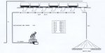
On arrival at the surface (C1 in Fig. 5 is the incline conveyor), material is stacked
onto dedicated stockpiles by means of a stacker (as in the upstream sections, stockpile number seven
is dedicated to waste). These stockpiles are the back battery limit of the simulation model. Material
is reclaimed from the stockpiles by underground variable speed vibrating feeders (each stockpile has
three units) according to the current demand by the plant. Waste is continuously reclaimed at a low
speed to the waste dump.
Fig 5: Incline conveyor and surface stockpile section
In order to test the effect of equipment availability, the following availability factors were
assumed based on the operating experience in similar environments (refer to Table 1). All breakdowns
were related to busy time, when equipment was actually doing some work as opposed to available time,
when it was working and/or idling.
Description |
Availability |
Cycle, hrs |
MTTR, hrs |
MTBF, hrs |
| Feeder |
92.00% |
168.0 |
13.4 |
154.6 |
| Vibrating grizzly |
98.00% |
720.0 |
14.4 |
705.6 |
| Crusher |
90.00% |
24.0 |
2.4 |
21.6 |
| Conveyor (excl. incline) |
90.00% |
8.0 |
0.8 |
7.2 |
| Incline Conveyor |
98.00% |
168.0 |
3.4 |
164.6 |
| Underground tripper |
98.00% |
168.0 |
3.4 |
164.6 |
| Surface stacker |
98.00% |
168.0 |
3.4 |
164.6 |
| Notes to Table 1:
Cycle - time basis upon which a breakdown occurs, for example 168h cycle means a
breakdown occurs once a week.
MTTR - Mean Time To Repair
MTBF - Mean Time Between Failures |
Table 1: Equipment availability factors
To conduct simulation experiments, the model was run for a period of a calendar year.
4. Discussion of Simulation Results
The criterion to judge whether the system is sized adequately, was measured in tons per annum delivered
to the surface, with minimum installed capacity and smooth operation, i.e. without overflow, blockages
or other disturbance in the material flow.
However, certain limitations were imposed on the size of the underground ROM and crushed ore bunkers,
normally resulting in a higher speed and uneven loading of the discharge conveyor, which will be
shown in the following paragraphs.
Because of the contamination issue and the requirement to convey only one material at a time, left and
right feeders in the underground crushing and screening section (refer to fig. 1, A8 Left/A8 Right) had
to be sized equally and sufficiently to reclaim the whole shift production. Initially those were
sized as per the nominal flowrate calculated with the formula below:
NormFlowRate = Shift Production / Shift Duration x Mine Efficiency
The first simulation experiment for the projected mine total output showed that the system could not
achieve the production target. The reason for this was unsufficient size of ROM and crushed ore bunkers,
which resulted in the following:
- Both the underground tripper and surface stacker had to move very frequently
because of small batches of material conveyed each time.
- The throughput capacity of the whole supply chain from the ROM bunkers to the crushed ore ones
was insufficient to remove quickly all material from the ROM bunkers, which resulted in overflow
situations and interruptions in the truck dumping.
- Blockages in the system when less than three grades of ore were mined within a shift (the random
sampling procedure allowed for the same material to be sampled twice and sometimes even three
times. In the real mining practice it is also quite possible that all three faces in a stope will
contain the same grade of ore). The blockages occurred primarily in the crushed ore bunkers,
dedicated to specific grades. Because of the insufficient size of the bunkers and the
need to service other bunkers as well, overflow conditions were noted which caused blockages of the
upstream process.
In order to improve the material flow and prevent blockages in the system, the sizes of all
underground bunkers were increased by 50%, and the throughput capacity of the link between them
was upgraded to 900 t/h. Further simulation experiments demonstrated that the system was able to
meet the production requirement.
Utilisation of equipment appears in Fig. 6, where equipment codes refer to the flowchart in Figs.
3 to 5. The following can be noted:
- The busy time of feeder A8 Right was shorter than for the unit on the left side, because it
serviced one ore bunker and one waste bunker, and discharged material on average three times in a
shift. The left side, with two ore bunkers, discharged material four times a shift on average.
- The utilisation patterns of the vibrating grizzly A11, crusher A16, belts A21 and B1 are very
similar except for the downtime. This is because all these elements are connected and form an
integral chain, although with different availability factors. The connected chain, however, can
only flow when all elements flow.
- Belts B7, Cl and G3 which also formed a connected chain, display slightly different utilisation
performance, namely the incline conveyor was running for a slightly longer period of time than the
other two belts. This can be explained by the different transport delays of the belts and regular
changeover of conveyed material and clearing gaps in between. The incline conveyor being the longest
one in the system with a transport delay ±4 times longer than the rest of the chain, could still flow
even though the upstream belt broke down, provided that this happened soon after a changeover.
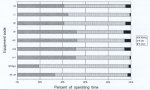
Fig. 6: Utilisation of equipment
The next round of simulation experiments had the objective to quantify utilisation factors for the
incline conveyor specifically, to allow for a cost-effective selection of the belt during
different operating periods, depending on the yearly mine production. The results of those
experiments are summarised in Table 2.
Table 2: Utilisation of incline conveyor at various annual production rates
t/h |
1.00 M t/a |
1.25 M t/a |
1.50 M t/a |
1.75 M t/a |
2.00 M t/a |
200 |
N/A |
N/A |
N/A |
N/A |
N/A |
420 |
41.60% |
N/A |
N/A |
N/A |
N/A |
600 |
29.36% |
36.86% |
43.40% |
50.18% |
N/A |
720 |
24.45% |
30.78% |
36.29% |
41.21% |
46.68% |
The main factor to bear in mind for a correct interpretation of the results is the speed of emptying
the crushed ore bunkers. For example, for a 1.0 M t/a total mine production roughly translating in
3 x 500 t of ore and 200 t of waste in a shift, it takes 9 h to clear only the ore bunkers with a
200 t/h incline belt.
It was observed in the model, that after a short time, levels in all crushed ore bunkers started to
rise, and then the bunkers became full, blocking the entire upstream operation. Therefore, a 200 t/h
belt was a definite no-go option.
With other belts, it was noted that once the incline conveyor busy time approached ±50%, it was no
longer capable of maintaining an adequate speed of material discharge from the crushed ore bunkers,
which caused overflowing and eventually, blockage of the system.
With a changing input feed-rate, the size of the surge buffer and the capacity of the discharging
conveyor must be traded off. As a rule, the conveying rate can be reduced (however, at a cost of
longer operating hours) with a larger surge capacity, and visa versa. In this particular environment,
the rated capacity of the incline conveyor had to be sacrificed in favour of the limited capacity of
the crushed ore bunkers, and the belt had to run fast though during a short period of time. On the
other hand, it was difficult to gain a significant reduction of the belt rated capacity, for the size
of the crushed ore bunkers had to be increased to accommodate the entire day production, However with
a real possibility to mine only two or even one grade of ore within a day, the size of those bunkers
would have to exceed 3000t, which was technically unfeasible.
Utilisation factors indicated in Table 2 were superimposed on the long-term mining plan, which allowed
the identification of points in time of the incline belt replacement, It was found that a low-rated
temporary belt could still be used in the approximately first 2 years of operation, which then needs
to be replaced with a medium-rated belt, which will serve for approximately another 12 years. Only
after that time will a full-size conveyor belt have to be installed.
5. Conclusions
Because of randomly occurring events like ore grading or equipment breakdowns and because of
multi-variant conditions inducing various control actions, conventional techniques like linear
programming could not produce confident results. Dynamic simulation appeared the only viable option
to solve the problem.
The first advantage of applying simulation modelling for this specific project is the right-sizing of
the underground infrastructure for a new mine, which although resulting in larger sizes of the
underground bunkers and of the link in between than originally allowed for, will ensure sufficient
capacity to meet a long-term mine production. Taking into account that the said bunkers will not be
erected structures but something like ore passes in the earth, the additional capital requirement is
negligible compared to the cost of production losses in the future.
The second benefit is the cost-effective approach to the phased replacement of the incline belt, which
will reduce the cost of sinking the shaft and improve the cash flow specifically in the initial mining
phase.
Acknowledgements
The authors express their appreciation for the support during the project execution and thanks for the
permission to publish this paper to Reed Swatman & Voigt, the project manager, and to Avmin Limited,
the project owner.
References
- MineSim'96 - First International Symposium on Mine Simulation via the lnternet: National
Technical University of Athens, Greece, 3-13 December 1996. Editors: G. N.
PANAGIOUTOU and J.R. STURGUL, A.A. Balkema Publishers (Holland) 1997.
- Mineral Resources Engineering: Special issue on mine simulation, Vol. 7 (1998) No. 3, Imperial
College Press, U.K.
- IJSM International Journal of Surface Mining, Reclamation and Environment: Special issue on mine
simulation, Vol. 13, A.A. Balkema Publishers, 1999.
- STURGUL, J. R.: Mine design: examples using simulation; Sot. of Mining Eng. (USA), 2000.
- LEBEDEV, A. A.: Simulation modelling of bulk conveying systems; Simulation (USA), Vol. 70
(1998) No. 2, pp. 90-103.
- STURGUL, J.R. and THURGOOD, S.R,: A simulation model for a materials handling
system for a surface mine; bulk solids handling Vol. 13 (1993) No. 4, pp. 817-820.
- LEBEDEV, A.A. and STAPLES, P.: Simulation of materials handling systems in the mines: Two
case studies: Simulation, Vol. 70 (1998) No. 3, pp. 183-196,
- LEBEDEV, A.A.: Benefits of simulation modelling for the mining industry, Latin American Mining,
Sterling Publications (U. K.) 1999.
ALEXANDER A. LEBEDEV received
M.Sc. Cum Laude and PhD degrees in metallurgical engineering from the
Moscow Institute of Steel and Alloys, where his scientific interests concentrated on application of
computer modelling to heat transfer and process control. He relocated to South Afhca and was employed
as a senior consultant with Xcel Engineering and Management, a industrial engineering and information
technology consulting firm, where he was actively involved in logistics, system engineering and
simulation modelling of large industrial systems. In 1999 he established his own consulting practice
in Operations Research and Management Science. |
 A.A. LEBEDEV |
 P. STAPLES |
PHILIP STAPLES graduated with a
B.Sc. in mechanical engineering from University College, Swansea, U.K.
He now works in South Africa designing high-tech conveying systems and stacker/reclaimers for the coal
and base metal industries. He left Bateman Materials Handling Ltd. in 1993 and is now a Consulting
Engineer in his own company. Mr. Staples utilises the Conveyor Dynamics, Inc. software in South Africa,
offering advice and support to the mining industry. |