BELT CONVEYOR DRIVES - A CONSIDERATION OF SOME
DESIGN ASPECTS
J.H. Rall Pr.Eng., BSc Eng., MSAIME
Hansen Transmissions (Pty) ltd
P. Staples Pr.Eng BSc, MSAIME
Managing Director Conveyor Knowledge and Information Technology
(Pty)Ltd (CKIT)
Summary:
This is a short review of part of the link between the electric power
grid and flat rubber covered belts used for transporting large volumes of granular material.
It is concerned with high volume material conveying and not with special cases such as feed or
metering conveyors, steep inclined conveyors etc. It considers mainly the speed reducer between
motor coupling and drive pulley, ratings, bearing life, service factors, stopping and anti-runback
devices.
1. General:
The ever increasing rate of consumption of earth's raw materials has brought
with it a need for faster movement of these materials from the point of extraction to the point
of process or usage
and transporting these materials through the process plant and disposing of the waste in the
shortest possible time. Many methods of material handling are employed from wheel barrows to
dump trucks or shuttle cars, to pneumatic ducts carrying pulverised particles in an air stream.
In this line of movement, belt conveyors play a very important part in the reliable
carrying of material over long distances at a competitive cost.
Each method of material conveying has its advantages and disadvantages.
One of the problems with belt conveyors is that soft friable material can be degraded,
particularly in loading and unloading. If the maintenance of lump size is important, this
can present difficulties on a complicated conveyor system.
Conveyor systems have become larger and more complex and drive systems have also been going
through a process of evolution and will continue to do so.
Bigger belts require more power and has brought the need for larger individual
drives as well as multiple drives such as 4 drives of 1000 kW each on one belt. Shaft mounting
of the complete drive
unit is another change which has brought with it the requirement
for more compact and lighter drive units. This tends to favor
a right angle drive configuration with the motor next to the belt and hardened gears to reduce
the dimensions and mass of the drive.
2. Drive Ratio and Belt speeds:
Depending on the quantity, size, distance and characteristics of the material
to be conveyed, the absorbed power, width, tensile requirements and top cover thickness of the
belt will be decided.
Large volume conveyor belts run in the range of 2 to 6 metre/second and the
allowable bend radius of the belt
determines pulley diameters which for large belts is of the order of 0,8 to
1,5 m giving pulley speeds between 50 and 125 rpm.
Assuming that 4 pole motors are used, this gives a reduction ratio required
between 12:1 and 30:1.
Most modern gear manufacturers do not use a higher ratio per stage than 5:1,
which means that speed reducers will be either 2 or 3 stage reduction. (Except for small powers
where worm reducers, or torque arms and V belt drives may be used).
There is a misconception that one can reduce the cost of the gear-speed reducer
by using a 6 or 8 pole motor, but even an 8
pole motor on the higher speeds would require a reduction above 6:1 and a 2 stage unit would
still be required. The bulk of
the cost of a gearbox is related to the low speed shaft torque
and therefore having determined this, there is generally no
economic advantage at all in using anything but a 4 pole motor. The motor manufacturers,
because of size and volume, generally supply 4 pole motors at the lowest price, and as a rule
therefore, a 4 pole motor is the best choice with a gearbox of the appropriate ratio to
arrive at the desired conveyor shaft
speed.
Where ball and roller bearings are used in the electric motors some manufacturers
prefer 6 pole or even 8 pole speeds for motors over 1000 kW.
3.1 Choice of Single or Multiple Drive.
Having calculated the power required to drive the belt and having considered the
belt tension and angle of contact, a decision can be taken on whether the belt should be fitted
with single or multiple drive.
This decision is often influenced by other equipment installed
in a plant and multiples of other smaller drives are often
used. Drive size may also be determined by the nearest standard motor available. Where a drive
point is situated some considerable distance from the main power source, a long cable may be
involved to supply electric power to the drive. In this case, the cable size
and cost of transformers may play an important part in the selection of number and size of
motors used. With direct on line starting, the peak current the motor will draw is likely to
be of the order of 6 x full load current and the combination of running current of a motor or
group of motors with the starting current of the last motor to start will
have a strong influence on the drive choice.
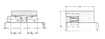
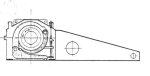
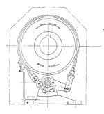
3.2 Method of Low Speed Shaft Connections.
Drive from the reducer to the belt pulley shaft is either by "flexible" coupling
from a drive pack mounted on a foundation next to the structure or by shaft mounted drive unit
hanging on the pulley shaft. When shaft mounted, the drive unit can be either hollow shaft,
driving through a friction locking
element or solid shaft attached by a rigid coupling to the conveyor shaft. Some typical attachments
are shown in the sketches. (See appendix A).
4.1. Choice of Starting method, drive size and Protection:
During start up of conveyor belts, a considerable mass is
usually involved which requires acceleration, and to reduce the length of time that the motor
draws starting current, a "slip coupling" is fitted between the drive motor and speed reducer.
Alternatively, slip ring motors are used to achieve a quick but gentle start up with control of
the peak current. On small
belts below 10kW direct on line starting directly coupled is quite normal and on belts, say below
100 kW D.O.L. starting
with "slip" couplings is most common, and probably the simplest and most cost effective. On
larger drives with power at its present continuously increasing cost, slip ring motors may
be attractive, due to the prevention of the peak, particularly
where maximum demand plays a part in the electricity tariff.
There is a multitude of slip couplings on the market for use with D.O.L.
start motors, but for larger belts the majority in use are liquid type couplings, either
straight traction or traction with delayed fill or controllable fill (scoop type).
A fluid coupling will always "slip" a small amount and will help multiple drives to share load,
provided the coupling
"fill" has been carefully adjusted. As a rule, each coupling has a slightly
different characteristic and if adjusted to share load correctly under full load conditions
will more than likely not share properly under light load conditions. Motor characteristics
also vary a little and can also contribute to poor load sharing on multiple drives. Drive systems
commonly go up to 4 motors per belt, but rarely more.
4.2 Motor Starting: (D.O.L. with fluid coupling).
On multiple drives accepted practice is to start the motor on the secondary
drive first and say 3-5 seconds later one of the primary drive motors and then the next primary
motor say
5-10 seconds later.
In practice, however, the observed starting procedures and
delay times vary a great deal. A very common sight is to see the secondary drive motor running
and due to conservative coupling selection, the starting current drops somewhat, but starts
rising quickly again due to the delayed fill coupling increasing it's slip torque, while the
belt remains stationary. If a primary drive is started at the correct time before the coupling
torque has increased too far, the belt is brought into motion much quicker with a lower overall
current. The relative slip of the coupling affects it's torque and so the motor current, and the
sooner the belt can be moved, the sooner the current peaks will drop.
In the case of scoop controlled fluid couplings all motors
are started in quick succession and then all couplings filled slowly. A similar procedure is
followed with slip ring motors and these two methods are undoubtedly the kindest to the belt,
pulley and lagging etc.
The choice of scoop type fluid couplings or slip ring motors
is likely to lead to the use of smaller motors with safety and possible savings on switch gear
maintenance.
4.3 Other Drive Methods:
Where a variable conveying rate is required, D.C. drives can be
used as well as squirrel cage motors with frequency control. Another method
is by hydro-static drive; again ideal for variable speed, but overall running and maintenance
costs on
big powers are likely to be higher than a fluid coupling drive, with S.C. motor or slip
ring motor.
4.4 Belt Protection:
Belt protection against overload and stalling is commonly done by a
centrifugal switch driven by a roller on the underside of the
belt. This, however, is not very sensitive and more sophisticated methods are now used.
One method consists of fitting a pulse generator to the drive gearbox low speed
shaft and similar pulse generator to a roller driven by the belt. A monitoring unit compares
the pulse frequencies continuously and if they go outside set limits, an alarm is given or the
belt stopped. On start up, belt slip can
be kept to a minimum by using the monitoring unit to control
the start up on slipring motors. The monitoring unit can control the rotor resistance and so the
starting torque. Alternatively, the "fill" of a variable fill fluid coupling can be controlled
by the comparitor.
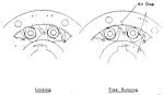
5. Stopping a Belt Conveyor
5.1 Forward stopping.
As a general rule, friction will reduce the normal forward
speed of the belt and load and bring it to rest in a relatively short time. The allowable time
for stopping depends mainly on the discharge end conditions. Where one belt feeds onto another,
tripping conditions, transfer bunker size and belt layout may indicate a need for a belt to be
slowed down by other methods than normal friction.
On a downhill section of a conveyor discharging onto a level or uphill belt is
generally the place where braking is required.
If one belt runs on longer than the rest of a system of conveyors, bunkers or transfer
chutes can be overloaded and may even be a hazard, but this is generally a very rare
condition.
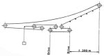
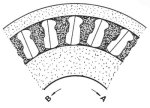
Considering a conveyor layout as per sketch (see appendix B)
fitted with a brake on the gearbox high speed shaft, it can be
seen that when stopped under load the inertia of the load would
tend to pick up the gravity tensioner and release the tension in
the belt between drive and head pulley and may even go slack by
the time the load comes to rest. The load assisted by the gravity take up would then
accelerate the belt in the return direction
while the drives are stationery with brakes on. When the belt between drive and head pulley
becomes tight it has to retard the load in a fraction of the distance in which it had been
accelerated.
Under this sudden stopping of the load the drive is subjected to heavy shock. In this case,
a brake is not only unnecessary, but highly undesirable.
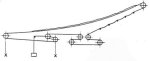
A brake fitted on a downhill belt drive would again release tension between
drive and head pulley and pick up the take up, but this would tend to release tension on the
driving (or stopping) pulleys and allow the belt to slip. This can damage the belt and pulley
lagging and can also be dangerous. The proper method of stopping a belt like this is on the
tail pulley or other pulley on the return belt after it leaves the take up.
Another application where brakes are sometimes used is on
belts running through a mobile stacker, to reduce the risk
of the belt snagging; should the stacker be moved while the belt is stationary. Here again a
brake would be fitted to the tail pulley and a holdback to the drive or head.
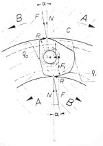
5.2 Reverse Stopping:
Uphill conveyors normally only need an anti-runback device.
This can be fitted to the head pulley or on one of the drive pulleys or to the gearbox. If fitted
to the gearbox, the
torque which the holdback is required to resist is reduced by
the ratio of the gears between the holdback and drive pulley. (See appendix C). Considerable
savings can therefore be made on the size of holdback fitted to the gearbox compared to that
required on the head or drive pulley. However, on multiple drives there can be
problems with load sharing. On normal running and start up,
the driving load is shared between the various drives by either
fluid couplings or slip-ring motors as previously mentioned.
When being held by a holdback fitted to the gearbox, the system
is torsionally much more rigid than in the drive direction and
it is highly unlikely that more than one gearbox / backstop
combination would hold the belt unless specific provision is
made for load sharing.
On a continuously inclined belt, (which is the worst,) at the moment of coming
to rest, the friction load can be considered
not to play any significant part in holding the belt back and
the full driving torque has to be considered acting in the reverse direction. On a multiple
drive in this situation, if
the strength of one gearbox is sufficient to resist the runback torque, then a holdback on one
gearbox will be adequate. Alternatively, more than one gearbox has to be fitted with a holdback
and some means of load sharing provided. (See appendix D for holdback sketches).
In many cases brakes are fitted together with holdbacks. If both the brake and
holdback have each been selected for a
torque somewhere near the driving torque, then clearly on runback condition with brake and
holdback working together, their combined torque is likely to be considerably higher than
the gearbox rating. Returning to the sketch of the conveyor just discussed, the brakes will
bring the drive pulleys and gearboxes to rest long before the load. Consider the gearbox high
speed shaft fitted with brake drum and holdback both
locked against reverse motion. When the belt suddenly applies reverse drive to the pulley, the
holdback and braking torque
has to be overcome and the brake drum accelerated through the gearbox as speed increases. In
this situation, an incredible stress is placed on the drum, low speed coupling and
gear-train.
6. Service Factors: (See appendix E for service factors
recommended by AGMA).
6.1 Gear Rating:
The use of a service factor is often regarded as a factor of ignorance by
the end uses. It may well represent the ignorance of the drive suppliers of the true
conditions.
In broad terms, gears rated according to the AGMA method of calculation will
transmit the rated load continuously,
with a risk of tooth failure of less than 1% due to surface durability or strength provided
that no shock loads are applied, no bearings fail, no material defects exist, load bearing is
perfect and lubrication is perfect etc.
In practice, a steady load is not very common, neither are bearings which do
not wear or absolutely rigid housings, shafts etc.
A service factor should therefore be selected with due consideration of the
actual conditions and not in "ignorance from a table"
6.2 Load Conditions on Teeth and other Components:
The loading and stress on any one gear tooth will vary from
zero to maximum once per revolution tensile on one flank and
compressive on the opposite as long as it runs and drives in one direction.
If this same drive unit is used on a reversible
drive, the variation of stress on a tooth is therefore
increased as both flanks of the teeth are subjected to tensile
and compressive stress and the range from maximum to minimum
nearly doubled and the fatigue life of the teeth considerably
reduced. Even under steady load conditions in both directions,
the 1% chance of failure will no longer apply.
Another potential problem area on reversible drives is keys and keyways. Keys
invariably have a very small amount of side clearance which will move from one side of the key
to the other
on reversal. The effect this has will mainly depend on the
amount of clearance and the shock which is applied. This is normally a maximum under start up
when backlash between the
teeth, coupling, elements etc., are likely to be open particularly on the reverse start up
condition.
Reversal of stress in drive components can also occur on units running only in
one direction, for instance, where brakes are fitted to slow the belt down.
The above for instance, applies equally to the low speed shaft couplings where a
spring element on a reversing conveyor may fail in fatigue where an identical drive on a
unidirectional conveyor shows no sign of fatigue.
The choice of brakes on conveyor drives appear to be selected
to suit the drive motor torque or more. On a crane, this may be
a valid starting point for brake selection, but on a conveyor
which may have up as well as downhill sections, the motor
torque is likely to lead to the selection of much too large a brake.
On the use of service factors, it is common practice to select
a gearbox with a minimum service factor calculated on installed
motor power. The motor power is often arrived at by doing very extensive and
careful calculations of the power required to drive
the belt which in simple terms will consist of power to overcome friction plus
power to lift the load. In both cases, an absolute maximum can be taken and then a contingency
factor added.
The efficiency of the fluid coupling can then be estimated, to be extremely low and
so also the gearbox efficiency. Apply a
service factor on top of this, then select the next bigger standard motor and the
drive motor will be able to cope with the most adverse freak condition with power to spare, but
do a fair amount of
damage to the belt, pulleys etc.
The last thing one wants to do is select a drive unit too small, but it is
essential to do all the calculations accurately and
then apply a "contingency" factor only once. The consequences
of selecting a gearbox or a low speed shaft coupling on drum
shaft too large would produce an uneconomic solution, but would give a very long expected
life. However, selecting too large a motor will have quite the opposite effect on the life of
a belt, pulleys, gearboxes etc., over an extended period of time. As an example, consider a
conveyor drive calculated to require 70 kW to drive it and add a 50% contingency factor.
indicating an absolute maximum 105 kW. The next bigger size of motor is say 132 kW.
On start up the drive train may be subjected to a torque equivalent to
2½ x 132 Kw = 330 kW while originally one set
out only needing 70 kW. On start up, the mechanical components of this drive will certainly
receive a beating.
Returning to the calculated rating of the drive unit; to ensure
that one maintains the chance of failure at the correct level,
the operating conditions have to be analysed and a S.F. selected
to ensure that shock and other unforseen conditions do not go
outside the factors taken into the calculation. It is accepted
that the calculated rating of a gear can be exceeded for short
periods without damage. For instance, it allows for a starting
torque of twice the AGMA rating of the gear without ill effect.
6.3 Bearing Life:
The normal methods of rating a ball or roller bearing in a
gearbox is to assume a B10 life of 5000 hours and calculate
the rated power of the gears for this bearing life which is then
taken as the bearing rating. The kW rating for bearings will
therefore normally be higher than the rating of the gears.
The generalised relationship between the life of roller bearing, the operating
load and rated capacity is expressed as:-
| Life = |
Constant
|
[ |
Rated load capacity |
] |
3,3 |
| |
Operating speed |
[ |
Actual operating load |
] |
|
When the bearing rating at a specific speed is calculated as stated above in terms of kW for
5000 hours B10 life and the average absorbed power of the driven machine is known, then the
expected
B10 bearing life will be:-
| 5000 |
* |
[ |
kW rating of bearing
|
] |
3,3 |
Hours |
| |
|
[ |
Absorbed average power in kW |
] |
|
|
Statistically more than 90% of all bearings operating under these conditions will have a
life at least equal to the calculated
figure or the chance of failure is less than 10% in this period
of running time. This is a statistical probability based on the assumption that the actual
life will be normally distributed and
the 10% failures include the possibility of a failure in the first minute of operation.
likewise the 90% which will exceed this calculated
life will include some which will have infinite life as the tails
of the normal distribution curve stretch from zero to infinity.
For other chances of failure, the bearing manufacturers give the following
factors with which to multiply the B10 life to calculate the expected life for the corresponding
chance of failure.
| Probability of failure |
10% |
5% |
4% |
3% |
2% |
1% |
| Factor |
1 |
0,62 |
0,53 |
0,44 |
0,33 |
0,21 |
The catalogue rating for a gear unit is the rating in kW of the weakest
element in the gear unit. Assuming the buyer requests
a S.F. of 1,5 on the absorbed power, and that a bearing is the
weakest element, then the expected bearing life will be approximately 19000 hours for a 10%
chance of failure or 4000 hours for 1% chance
of failure. The relationship between load and life is exponential
and a small change in load will have a significant influence on expected bearing life, therefore,
it is essential that the average absorbed power of the belt be calculated.
7. Conclusion:
To provide a first class solution to a materials conveying problem
an important point is a good integrated balanced design of which
the drive is one element which requires close and open collaboration between the conveyor
designer and the drive supplier. To this
end, may we suggest that when placing an enquiry for conveyor
drives of say over 100 kW, that the following information be
given:-
- A simple sketch of the conveyor layout.
- Calculated absorbed power in some detail such as:-
- Power to overcome all friction losses.
.............. kW
- Power to lift load. (If lift is involved).
.............. kW
- Power to move load on level. (Where level and lift involved).
__________kW
- a + b + c = Calculated normal total absorbed power.
========kW
- Contingency for overload and frequency expected (or chance of overload in %).
................kW
- Total maximum calculated absorbed power.
========kW
- Additional torque required to accelerate load
................ Nm
If this is more than 75% of the equivalent torque
Of (f), then it needs consideration in relation to
the motor characteristics.
- For purposes of bearing life calculation, the expected average continuous
absorbed power.
- Method of starting and expected start up time.
- Method of preventing runback.
- Size of motor (If not less that 'f' reason for choice).
- Expected service factor and reason for choice of S.F.
- Expected bearing life and acceptable chance of bearing failure.
The end user requires larger outputs for a specific capital costs
coupled to low energy consumption, low maintenance costs and
high reliability over a long operating life. One of the "elements in this "mix" is
the speed reducer for which the optimum choice
is at the present moment certain to be a helical gear unit with
shafts running on ball or roller bearing with hardened teeth
driven by an appropriate "mix" of electric motor and coupling
External Shrink Double Taper.
Appendix A1
Internal Friction Locking Elements
External Shrink Disc
Single Taper
Appendix A2
Internal Stretching Element
Appendix A3
Solid Shaft Rigid Coupling
Shaft Mounting for Gearbox
Conveyor Drive with
Friction Brakes
Appendix B
Normal Running
Full load trip
Brakes stop belt and load carries on picking
up gravity take up causing slack belt.
If brakes are required "X" is the proper place to apply them.
Gearbox Ratio 16:1 Then Torque
on Backstop 1/16th. of L.S.S. Torque
Appendix C
L.S. Gearset Ratio 4:1 Torque on Backstop
on Intermediate Shaft ¼ of L.S.S. Torque
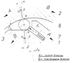
Roller and Ramp Type Holdback
Appendix D1
Sprag Type Holdback
4.2 Load classifications for various applications are given
in Table 2. They are classified into three commonly recognized
load classifications : Uniform, Moderate Shock, and Heavy Shock.
4.3 Service factors represent the normal relationship between gear
design power rating and the continuous power requirements. Applications involving unusual or severe
loading or requiring a high degree of dependability should be carefully reviewed
with the manufacturer before a service factor is applied.
4.3.1 Applications with high-torque motors and motors for intermittent
operations and applications where extreme repetitive shock occurs or where high-energy loads must be
absorbed, as when stalling, require special consideration and are not covered by the service
factors given in Table 1.
4.4 when drives are equipped with brakes on the input,
and the torque rating of the brake exceeds the rating of the
motor, the rating of the brake dictates the selection of the gear unit.
4.5 The recommended service factors for Dry Dock Crane applications are given
in Table 3. Due to
the nature of these crane drives, the service factors are to be used for any duration
of service.
4.6 When a fluid coupling is used between the prime mover and the gear unit,
the service factor given in Table 1 for moderate or heavy shock may be modified based on the
unit manufacturer's analysis and recommendation for the application.
4.7 The maximum momentary or starting load must not exceed 200 per
cent of rated load (1 00 per cent overload). Rated load is defined as the unit rating with a
service factor of 1.0.
4.8 The service factors listed for paper mill applications are
consistent with those shown in TAPPI (Technical Association of the Pulp and Paper Industry)
Standard 406.08, "Service Factors for Gears on Major Equipment in the Paper and Pump Industry."
Please note only one manufacturers prices were used for motors, fluid couplings and
switchgear. No allowance is made for supply cable size to cater for starting current.